
Uni-T UT390b laser distance meter front view
2013-07-27
Uni-T UT390b laser distance meter front view
UPDATE 2: Serial commands and timing information are now available here.
UPDATE: I've posted code to parse the serial datastream here.
This is a tutorial on how to get serial data out of a cheap handheld laser distance meter, which can be fed into an Arduino or a PC. You can use the distance measurements in all sorts of projects like robots and quadcopters. There are vendors who sell conversion kits that sniff the distance measurement off the LCD and output it over serial. The problem with those kits is that they cost more than the laser meter itself. Luckily I managed to find a laser distance meter that outputs distance measurements over serial directly: the UT390B from Uni-T which sells for about $56 from online retailers. Laser distance meters use precise electronics to measure the length of time it takes a laser beam to reflect back from a target. Handheld units like this one have a range of about 0.2m - 40m with a precision of 2mm. They're a great replacement for HC-SR04 ultrasonic sensors if you need long range measurements.
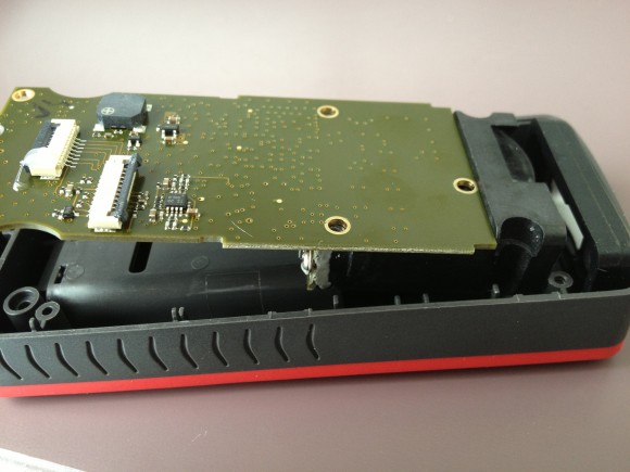
You can see the unit's debugging port underneath the battery cover. To take it apart, remove the 2 visible screws.
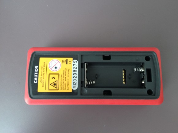
UT390b device with battery cover removed showing debug pins
Now you can pry off the cover.
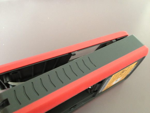
UT390b with front cover open
This ribbon cable connects the unit's keypad. Scrape off the glue and unplug it for now.

The ribbon connecting the two halves of the UT390b device
Next, remove the 2 screws with washers that hold the rubber piece at the front. If you want to remove the screen, it's connected by 4 clips to the circuit board. It's probably a better idea to leave the screen connected, so you can verify that the unit is working properly while you're testing your serial parsing code.
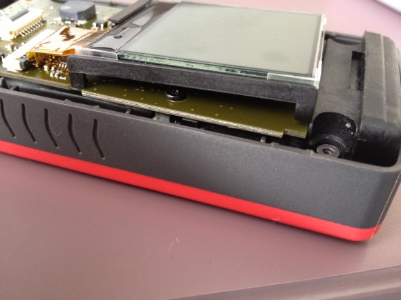
Removing the screen from ut390b device
DON'T remove these 3 screws. They connect the laser diode to the circuit board, and if you loosen these screws you risk breaking your laser.
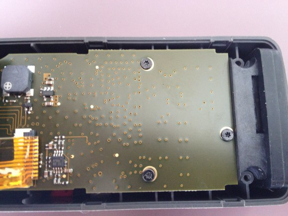
3 screws on circuit board which should not be removed
The easiest way to access the debug port is by desoldering the battery connector as shown below. Note: this photo shows the 3 screws removed. DO NOT do this, as it's unnecessary and could cause the unit to break in two.
Removing the ut390b circuit board (don't do this)
Finally you can solder some thin wires to the debug port. The pinout is as follows, seen from below the board.
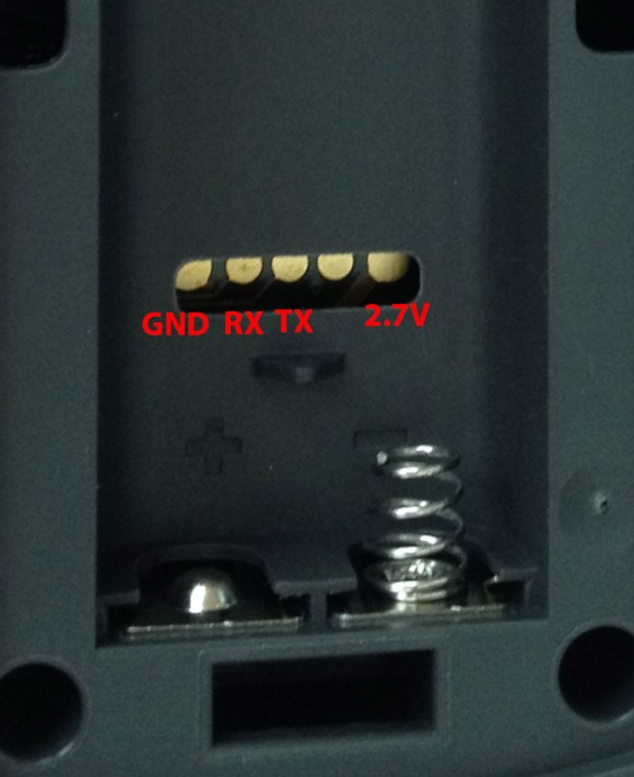
Pinout of ut390b debug pins. from left to right: GND, RX, TX,BOOT0, VCC (2.7V)
We can replace the original keypad with a microcontroller which can simulate button presses to control the unit. The keypad pinout is below. The ribbon connector is 8 pin, 1mm pitch. If there's enough interest, I will assemble and sell a small interface board to break out the necessary signals.

Pinout of ut390b keypad ribbon connector. From left to right: Unit, n/c, Func, On, GND, Mode, n/c, Off
This unit's serial port runs at 115200 baud (8N1). On bootup, it outputs the following text with \r\n line endings:
ldpara:395
curent ver:420411
Year:Jan 21 2013 Time:13:53:10
ldpara:395
Iint OK
APDMIN=136 APDMAX=167
BIASVOLMIN=2307 BIASVOLMAX =1718
Notice "APDMIN" and "APDMAX", which are likely calibration values for the avalanche photodiode used to detect the reflected laser beam. A few sloppy printfs as well.. To turn the unit on, connect the ON signal to GND for about 300ms. Once it's on, the ON signal is also used to take a measurement. After a measurement is taken, the unit outputs the following:
Dist: 2827,curtemp =21
V2.0
nDist: 2827,tempDv=0
The Dist and nDist values are in millimeters. As far as I can tell, the two measurements are always identical. If there's a measurement error (Error 154, out of range or sensor error) the unit will output:
OUT_RAN dist = 30If the unit can't determine the average distance (Error 160, sensor shaking too much or Error 155, signal too weak) the unit will output one of the following lines:
MEDIUM2 AND THIN NOT MATCH
MEDIUM1 AND MEDIUM2 NOT MATCH
THICK AND MEDIUM1 NOT MATCH
MEDIUM1 AND MEDIUM2 NOT MATCH
When you turn it off, it outputs:
SysPowerOff!
WriteTestData TRUE
Serial input?
I'd like to find a way to control the unit over serial. So far all I've found is that sending 0x23 ('#') or 0x73 ('r') will cause the unit to power down. It seems to ignore every other byte, as well as some common english words and modbus commands. If you manage to find any other byte sequences, email me or leave a comment below. If you liked this article, you might also like DORI, my robot project. DORI uses a slightly different laser distance measurement strategy. You can learn more on the project homepage and in my thesis.
wonderful article...thanks for the detailed explanation!!!
Thank you very much!
Where did you find a ribbon cable and ribbon cable connector to solder to? I'm having trouble finding one.
Waw, this is what I need, Thank you very much
I found several compatible ribbon cables inside a broken HP laptop with 1mm pitch. They have more wires than needed, but they can be carefully cut to width and soldered up. I've also had success directly soldering to the back of the ribbon connector with thin enamelled transformer wire.
Very cool! When you send instructions for reading, what's the delay until you get a reading back? In other words, at what frequency can you get readings? I've noticed on my Bosch (that I haven't taken apart) that a reading takes in the order of 1-2 seconds and if it fails it times out in 5 seconds or so. This would make it less applicable for real-time sensing applications.
The delay is likely very similar to a Bosch meter. Individual measurements take from 1 to 3 seconds depending on the surface being measured and the physical stability of the meter. In rapid-fire mode (triggered by holding the ON button for about 1500mS), the sensor is able to output an average of 3 readings per second when measuring flat, solid surfaces. The commands that have been found so far are to take a single measurement, take 3 measurements, shutdown, and perform a memory dump. I'm still testing these commands and looking for more. I'll write another update to this post when I've got more info.
Awesome, thanks for the insightful answer! I wonder if it could be sped up by looking into the sensor readout / or timing it out earlier.
Thank you so much for this tutorial! This is exactly what I need to get my projecting working. I just received the meter and am planning to test it soon.
One question I have is about the serial connection. Do you need to convert the 5V signal from the Arduino to 3V for the meter? Or did you just connect the Arduino TX directly to the RX of the meter?
I use three 1N4001 diodes to drop the Arduino's 5V Tx signal before it's sent to the laser unit. Each one drops 0.6V - 0.7V, which leaves the TX voltage roughly around 3V. The laser unit runs at a regulated 2.7V, so technically it's still a bit high but I haven't seen any problems so far. Others have directly connected the laser to the Arduino's 5V signal but you never know what kind of damage that might do to the laser.
The laser's 2.7V RX signal is (barely) high enough to be seen as a HI signal by the AVR. For more reliable operation you can use a small MOSFET circuit to perform the level conversion.
You can also check out Microchip's 3V Tips 'n Tricks datasheet, available at http://ww1.microchip.com/downloads/en/DeviceDoc/chapter%208.pdf.
Hello! Can you make foto side back of board (with mcu)? What the mcu model is used in this device?
Thank you for this guide. It was a lot of details.
@qartis: I connected wires to GND, RX, TX pins and I was able to read the output. My problem right now is that I don't know how to trigger the ON button from an Arduino. Can you give me any hints? I have no problem with coding the Arduino or building a board based on a scheme.
Thank you
First, thank you for this post!
But unfortunately, I've have big problems using it as a manual.
I want to share a big problem while disassembling device.
In your manual you wrote: "Next, these 3 screws (Torx T5 size)." It was a bad advice for me. This 3 screws should not be removed! They don't hold the PCB - they hold laser module on it!
To take PCB off from case, you should desolder the battery connectors, remove 2 screws with washers (these screws already removed on your photos) and pull out a silver plastic detail from top side (from where laser is light) and that's all, PCB is easily removed then.
If this silver plastic detail is not removed, it is hard to take off PCB gently. In my case, I removed 3 screws holding laser module and was trying to take off PCB. Regardless of the fact that I succeeded (disassembled the device and solder wires for serial out) device become broke. After assembling all back device was not worked (no measure, it was some error code on the screen).
I've discovered that some copper contacts on laser module was detached while disassembling because 3 screws holding laser module were removed and it was holding only with solder connection. And it seems impossible to repair this because this is mulilayer PCB.
So again - these 3 screws holding laser module should not be disconnected!!!
Thanks it's fantastic. You know if the devices in the same series but with a greater range of distance work the same? For example:
http://dx.com/es/p/uni-t-ut391a-laser-distance-meter-red-deep-grey-70m-208042
or this
http://dx.com/es/p/uni-t-ut392-ultrasonic-laser-distance-range-finder-device-red-grey-199857
I'm very insteresting connect tu arduino.
Thanks
Joselito
I'm sorry for the bad instructions! You're right, there's no reason to remove those 3 screws at all (I think I just removed every screw I could find). I'll update the post to remove that picture to avoid confusion. Thanks for the clarification.
I haven't tried this procedure with any other Uni-T laser meters. I did manage to read the signal off a CEM brand LDM-40 meter by sniffing the SPI commands sent to the screen and reinterpreting the numbers that are displayed. But that technique is a bit of a pain compared to directly reading serial output.
If you do try it out, send me an update and I'll post the info here. Cheers!
if I try this. I will send the result.
Thanks
qartis
HI !
Thanks its very helpful.
I have a little problem. When I turn on the device it send me the basic informations but when I measure it doesnt send me the measurement's result. Any other messages are arrived (turn off message, error messages) But I see a little difference between our devices.
Your device:
curent ver:420411
Year:Jan 21 2013 Time:13:53:1
My device:
curent ver:420408
Year:dec 5 2012 Time:12:01:38
Maybe this is the problem. I dont know.
Have you any idea ?
Hello,
I recently bought one UT390B from DX, I soldered the wires as indicated, then I connected the RX, TX, GND, and 2.7V to the RX, TX, GND and 3V ports, but I can't print the basic information nor any measurement. Have I done anything wrong?
Thanks in advance.
Andfoy
awesome work! I could use something like this for my business to measure size of packages and store the results for shipping calculations
Hello,
I only connected RX,TX and GND not 2.7V. It's work well.
regards
Does anyone know what the datastream item curtemp means? Is it the internal temperature of the unit or is it the temperature of the surface the laser is pointed at?
Can this meter find reliable result if not pointed straight? like 45 degree and also on rough surface?
I suspect that it's the unit's temperature, because I think if they were taking infrared temperature measurements they would advertise that as a feature of the laser unit.
It tends to do fairly well on most surfaces, and at most angles. It has some difficulty on pure black surfaces, and some scattered surfaces like grass and thin cloth.
The pin on the exposed port that is between TX and 2.7V goes to the BOOT0 pin of the STM32F103C8T6 ARM Cortex M3 processor.
There seems to be an error in the article. Looking at the ribbon cable, the pin next to "on" that was labeled "gnd" appears to be 3V.
If you measure the voltage from the gnd pin in the exposed port to the pin "gnd" of the ribbon cable. The voltage measures +3V with respect to the exposed port gnd.
Also, if you short the ribbon cable "on" and "gnd" (3v?) pins the unit turns on. This suggests that to turn the unit on the "on" pins should be pulled to 3v not gnd as stated. You can also test shorting the exposed port's gnd to the ribbon cable "on" and nothing happens.
But... What about eye safety?
What about the frequency that it can read? It the laser on the entire time? Or do you need to trigger it?
with the code of dardan on the second page, the laser once powered up by the power button, will take measurements automatically, and output it to the serial console of the arduino ide
Would it be possible to switch the unit on via serial? Or is this very wishfull thinking?
So far nobody has found a way to turn the unit on without using the "on" button signal. Paradug found that the 4th debug pin connects to the processor's BOOT0 pin, which is probably used to enable a bootloader at startup to reflash the unit during testing (but can't turn the unit on). If I find a better way to turn the unit on I'll post an update here.
If there is a much more simple way of getting measurement data from a laser measurement module - would you all be interested ? Like just sending a read command and getting the measurement data back in plain and simple format.
It looks like power can be applied directly to the exposed Vcc pad, skipping the power switch circuitry and directly booting up the unit. After a little testing, I've found that at 2.8V the unit operates normally and the battery charge indicator is at 100%. I've designed a small breakout board that will fit into the battery compartment and attach to the debug headers via pogo pins. I'll post an update when the first batch of boards arrives.
Yes, I would like to see i2C output or PWM
Yes, It is available in UART port with simple command interface.
Let me know if you want to purchase.
I have modules that can be controlled via Serial UART port for reading laser distance measurement results.
Really simple - interested ?
Hi, i read here on your blog that this device can take measurements at a rate of 3 measurements for 1500msec. But can this device measure for more minutes continuously ? Or is that 1500msec the max? thanks.
A similar mod-kit device is available for the Fluke 414D:
http://www.porcupinelabs.com/lr4
Perfect Prime .. do you have a link to specs and price?
Any update on the Breakout Board?
The "Power on" ability is really important for what I'm working on.
Directly wiring sounds ok thoughm but a board would be classy.
I'm assembling the prototype breakout boards now. I'll post an update on the blog in a week or two with the results. There are 10 boards in this first batch, and I will give them away on a first-come-first-served basis (just pay for postage).
Hi, can you please tell me the size of the slot hole for the debug port? the one that is under de batteries cap. thanks in advance
I would like more information on this if you can provide it. Thank you
what is the cost of this sensor???
I'm going to try one of these to see if it works!
http://www.dxsoul.com/product/40m-1-8-lcd-laser-distance-meter-range-finder-black-green-901434545
Thanks so much for this article.
Has anyone figured out how to disable the buzzer? I don't see it on the PCB. Is it inside the laser module?
I planning to periodically measure the salt level in our house water softener and would like it to take the measurements quietly.
Found it! It's the grey square component with the + on it next to the keyboard connector. I unsoldered it and now the meter is quiet.
The low cost ones do not have anything spit out. I'm going to see if a ST SWD type port can communicate with the ARM processor inside. It may be possible to still get something out of it but by default the serail port is NOT ON as in the Uni-T version of this article.